Views: 0 Author: Site Editor Publish Time: 2026-10-14 Origin: Site


Internal turning ranks among the most demanding operations in modern CNC machining. A solid carbide boring bar provides the ultimate precision required to properly enlarge or finish an existing hole. Manufacturers engineer these cutting tools entirely from cemented carbide rather than standard steel or heavy metal. Machinists constantly battle tool deflection, severe vibration, and poor chip evacuation during deep hole operations. These inherent challenges quickly lead to compromised surface finishes and scrapped out-of-tolerance parts. Standard steel bars simply lack the static stiffness necessary for deep reaches. Solid carbide directly solves this problem by offering a vastly higher modulus of elasticity. You will learn how these rigid tools successfully overcome extreme length-to-diameter ratios on the shop floor. We will also explore essential tool configurations, proper clamping techniques, and setup practices to maximize your machining stability.
Solid carbide boring bars provide 2 to 3 times the rigidity of standard steel bars, enabling stable machining at L/D ratios up to 8:1 (or higher with specialized setups).
While they dramatically reduce chatter and improve surface finish, they require highly rigid machine setups due to carbide's inherent brittleness and susceptibility to shock damage.
Integrating a carbide boring bar with internal coolant is critical for deep-hole chip evacuation and thermal management.
Upfront tooling costs are higher than steel, but ROI is realized through reduced scrap rates, faster cycle times, and improved insert tool life.
Internal machining creates complex physical challenges at the cutting edge. The bar extends deeply into the bore. Cutting forces naturally push the tool away from the workpiece. We call this phenomenon tool deflection. Steel bars absorb these forces by flexing. This flexing creates a springboard effect inside the bore. The tool bounces off the material rather than shearing it smoothly. Deflection becomes exponentially worse as the tool extends further. You simply cannot machine a perfectly straight hole when your tool continuously bends away from the cut.
Chatter and deflection carry immense financial penalties on the shop floor. They lead directly to scrapped parts and material waste. Vibrations also accelerate insert wear prematurely. You end up replacing cutting edges far more frequently. Furthermore, machinists often slow down feed rates to compensate for the vibration. This reactive measure creates massive production bottlenecks. Your cycle times stretch out unnecessarily. The business loses money on both ruined materials and wasted spindle hours. Upgrading your tooling often eliminates these hidden quality costs entirely.
Machinists rely on the length-to-diameter (L/D) ratio to select appropriate tooling. You calculate this by dividing the bore depth by the tool diameter. The industry establishes a strict baseline rule for steel. Steel bars generally fail when the boring depth exceeds four times the bar diameter (4xD). Pushing a steel bar past 4xD guarantees severe chatter. You will experience terrible surface finishes. Tolerances become impossible to hold. This 4xD threshold marks the exact point where standard steel tooling becomes physically inadequate for the job.
Many shops treat the symptom rather than the root cause. They slow down speeds or take lighter passes. Transitioning to carbide addresses the actual mechanical failure. Solid carbide possesses three times the static stiffness of standard steel. It resists the cutting forces pushing against it. You gain a massive increase in static stiffness. This prevents the tool from bending in the first place. You solve the root cause of the vibration. Machinists can maintain aggressive feed rates while easily holding tight tolerances.
Comparison: Steel vs. Solid Carbide Boring Bars
Feature | Standard Steel Bar | Solid Carbide Bar |
|---|---|---|
Maximum L/D Ratio | Up to 4xD | Up to 8xD (or 10xD optimized) |
Rigidity / Stiffness | Low to Moderate | Exceptionally High (3x Steel) |
Vibration Resistance | Poor at deep reaches | Excellent damping properties |
Shock Tolerance | High (Forgiving) | Low (Brittle, prone to cracking) |
Standard solid carbide configurations dominate general internal turning tasks. They utilize standard indexable carbide inserts. You can swap these inserts quickly when the edge dulls. Manufacturers braze a steel head onto a solid carbide shank for many of these tools. This hybrid approach allows the tool to house standard clamping screws. You get the immense rigidity of the carbide body. You also maintain the flexibility of conventional insert geometries. They perform exceptionally well for standard finishing passes in deep bores.
Miniaturization drives modern medical, aerospace, and electronics manufacturing. Hole diameters frequently drop below four millimeters. You cannot use traditional insert bars in these tiny spaces. Instead, you need a highly specialized tool. Implementing a micro boring bar for CNC lathe internal turning solves this space constraint. These tools feature a cutting edge ground directly into the solid carbide blank. They offer maximum structural mass. You can successfully turn microscopic internal profiles while eliminating chatter.
Sometimes you need extreme dimensional accuracy for specialized internal geometries. Miniature threading, grooving, or complex profiling demands unique tool shapes. A standard turning insert simply will not fit. In these scenarios, evaluating a solid carbide micro boring cutter for precision micro boring becomes necessary. Engineers grind these cutters to exact custom profiles. They handle very tight internal clearances perfectly. You achieve flawless surface finishes on intricate internal features. These profiled cutters remain indispensable for high-precision miniature component production.
Complex parts often feature internal counterbores or hidden chamfers. Reaching these features typically requires flipping the part into a secondary machine setup. Secondary setups destroy concentricity and waste valuable production time. You can eliminate this step entirely. Utilizing a reverse boring bar for internal metal machining allows you to pull-bore these features. The tool passes through the main bore. It then cuts backward as the machine pulls it toward the spindle. You machine the hidden feature perfectly in a single setup.
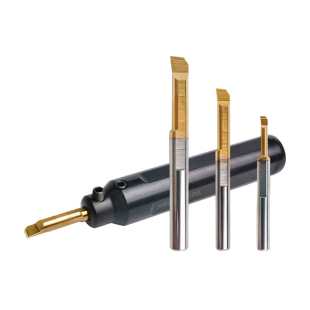
Not all solid carbide tools share the exact same composition. Manufacturers blend tungsten carbide powder and cobalt binders in varying ratios. You must evaluate the specific carbide grade. A lower cobalt binder content yields higher rigidity and hardness. This strictly prevents chatter during continuous finishing cuts. However, this high rigidity increases the brittleness of the tool. You face a higher risk of catastrophic tool failure if your bore contains interrupted cuts. You must balance hardness against toughness based on your material.
Deep hole boring generates massive amounts of heat. It also traps metal chips inside the blind hole. These trapped chips will destroy your surface finish if the tool recuts them. Standard flood coolant rarely reaches the bottom of a deep bore. Assessing the need for a carbide boring bar with internal coolant is critical. High-pressure through-coolant flushes chips out forcibly. It lubricates the cutting edge directly. This prevents chip packing and catastrophic tool breakage entirely.
Your cutting tool is only as rigid as its holding mechanism. A highly rigid bar requires an equally rigid holder. Many older tools feature cylindrical shanks milled flat on one side. Machinists lock them down using basic set screws. This method creates point-stress on the brittle carbide. Today, you should compare standard holders against specialized quick-change or high-precision collet systems. Collet systems wrap around the entire shank. They provide uniform clamping pressure. They significantly increase overall assembly rigidity.
You must select a bar with the proper cross-sectional geometry. The goal is to maximize the physical mass of the tool. More mass equals more vibration dampening. However, you must also leave enough empty space for continuous chip evacuation. If the bar is too thick, chips will jam against the bore wall. This jam will instantly snap a brittle carbide tool. Ensure your chosen geometry strikes the perfect balance. It needs high core strength plus adequate flute clearance.
Carbide offers zero flexibility. It simply does not bend under extreme pressure. It breaks instantly. You must address this primary risk before implementation. A minor machine crash will shatter the bar into pieces. Excessive feed rates will also snap the tool. When standard steel crashes, it bends. You can often salvage the setup. When carbide crashes, it shatters. This results in incredibly high replacement costs. Operators must double-check their tool offsets carefully.
Carbide tooling cannot compensate for poor machine maintenance. A loose or worn machine spindle will transfer vibration directly into the rigid tool. You must ensure your lathe is mechanically sound.
Avoid set screws: Direct metal-on-metal point contact causes stress fractures in the carbide shank.
Use split sleeves: These bushings compress evenly around the bar, distributing the clamping force safely.
Utilize hydraulic chucks: They provide excellent runout accuracy and dampen micro-vibrations effectively.
Minimize overhang: Only extend the tool as far as absolutely necessary to clear the bore depth.
Following these setup rules maximizes surface contact and minimizes vibration transfer.
Centerline alignment dictates the success of internal turning. You must dial in the cutting edge to the exact center of the workpiece. Even minor deviations in center height ruin the cut. If the tool sits too high, the insert rubs against the material. This creates massive friction and poor surface finishes. If the tool sits too low, cutting forces pull it downward aggressively. This causes premature edge failure and chatter. Use a dial indicator to guarantee perfect center height.
We strongly warn against using solid carbide in severe interrupted cuts. Bores containing large cross-holes or deep keyways present a massive danger. The cutting edge repeatedly slams into the empty void and back into the metal. This creates violent shock loading. Because the tool is brittle, this shock will fracture the shank. If you absolutely must bore an interrupted cut, you must strictly optimize your feed rates. Reduce the depth of cut significantly. Consider specialized heavy metal dampening bars instead.
Your tool selection journey begins with basic math. Step one requires calculating the exact L/D ratio.
Measure the maximum required depth of the internal bore on your blueprint.
Determine the largest tool diameter you can fit while allowing room for chips.
Divide the depth by the tool diameter.
If the result exceeds 4, immediately shortlist a solid carbide solution.
Relying on this simple math removes the guesswork from tool selection.
You must evaluate your machine's internal plumbing. Check your main pump pressure specifications. Ensure your filtration system is clean and functioning. If you plan to utilize through-coolant tools, your machine must deliver adequate PSI. Low-pressure coolant will not clear chips from a deep hole successfully. It will merely create a metallic sludge at the bottom of the bore. Verify your machine can push coolant forcefully enough to clear your specific bore diameter.
Solid carbide requires a higher initial financial outlay than steel. You must justify this purchase through long-term performance gains. Compare the initial purchase price against your expected reduction in cycle times. Carbide allows you to push faster feeds and speeds securely. Calculate the savings from eliminating scrapped parts. Furthermore, perfectly smooth finishes often eliminate the need for secondary operations. You might entirely remove slow honing or reaming processes from your workflow. These time savings generate massive ROI.
Do not outfit your entire tool crib blindly. We highly recommend conducting a targeted Proof of Concept test. Buy a single carbide bar first. Run it on your highest-scrap part family. Alternatively, test it on a component with the tightest dimensional tolerances. Document the surface finish improvements. Track the exact vibration reduction. Validate the insert tool life extension. Once the single tool proves its financial value on the floor, you can confidently scale the implementation.
Solid carbide boring bars serve as highly engineered solutions for specific mechanical limitations in CNC turning. They are not blanket replacements for all internal tooling. You should deploy them strategically when steel tools fail at deep L/D ratios. Their unmatched static stiffness guarantees precision in the deepest bores.
Success ultimately depends on a holistic machining approach. You cannot simply clamp a rigid tool into a sloppy holder. You must combine the bar with proper 360-degree holding mechanisms. You must ensure precise centerline alignment. You must also guarantee effective chip evacuation via high-pressure internal coolant. Machinists and production managers should audit their current scrap rates on deep-bore parts today. Identifying these pain points will reveal immediate ROI opportunities for carbide implementation on your shop floor.
A: Generally, a switch is required when the boring depth exceeds 4 times the diameter of the bar (4xD). Steel bars flex and cause chatter beyond this limit. Carbide can successfully machine at ratios up to 8xD or even 10xD depending on how rigid your machine setup is.
A: They can, but it carries high risk. Due to carbide's brittle nature, shock loads from interrupted cuts can easily cause the bar to fracture. Heavy metal or specialized tunable dampening bars are often much safer alternatives for bores with severe interruptions.
A: In deep bores, chips cannot easily escape. A tool with through-coolant forces high-pressure fluid directly to the cutting edge. This flushes chips out of the blind hole entirely. It prevents chips from being recut, which would otherwise destroy the surface finish or instantly break the brittle tool.
A: Avoid direct set-screw contact against the carbide. Set screws create point-stress that cracks the shank. Use a split-sleeve bushing, a hydraulic chuck, or a precision collet system instead. These provide 360-degree clamping force, maximizing rigidity and preventing point-stress fractures.


