Selecting the correct boring bars for Swiss lathes is fundamentally an engineering problem of rigidity, tool deflection, and vibration control rather than simply choosing a tool that fits inside a hole. In high-precision Swiss machining, where components may contain internal diameters smaller than 6 mm and tolerances tighter than ±5 µm, the boring bar often becomes the limiting factor in machining stability. Because Swiss lathes operate at high spindle speeds and frequently involve long tool overhangs, factors such as boring bar material stiffness, length-to-diameter ratio (L/D ratio), chip evacuation efficiency, and cutting parameter optimization directly determine dimensional accuracy and surface finish quality. Understanding the physics behind tool deflection and vibration is therefore essential for selecting the optimal boring bar for micro internal machining.
Swiss-type lathes are widely used in industries such as medical devices, aerospace components, precision connectors, and micro-mechanical assemblies. These machines are designed to support the workpiece near the cutting zone with a guide bushing, reducing part deflection during machining. However, this design shifts the mechanical challenge toward the cutting tool itself. Small diameter micro boring bars and internal turning tools must extend into deep bores while maintaining rigidity under cutting forces. When the tool becomes too slender relative to its length, even a small radial cutting force can cause measurable deflection, leading to tapered bores, poor surface finish, and inconsistent dimensional control.
1.The Mechanics of Boring Bar Deflection in Swiss Machining
The most critical factor affecting internal machining stability is tool deflection. From a mechanical engineering perspective, a boring bar behaves like a cantilever beam subjected to cutting forces at its tip. The theoretical deflection of a boring bar can be described by the classical beam-deflection equation:
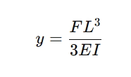
where
F is the cutting force,
L is the unsupported length (overhang),
E is the modulus of elasticity of the bar material,
I is the moment of inertia of the tool cross-section.
This equation explains why deflection increases dramatically with tool length. Because the length term is cubed, doubling the overhang increases deflection by eight times. For Swiss lathe boring operations where the tool may extend several diameters into the workpiece, this relationship becomes a primary constraint on achievable precision.
Material stiffness plays a key role in controlling deflection. The modulus of elasticity for common boring bar materials differs significantly. Steel typically has an elastic modulus of approximately 206 GPa, whereas tungsten carbide reaches roughly 550 GPa, making carbide substantially more resistant to bending under load. This difference is why carbide boring bars are widely preferred for small diameter and high-precision Swiss machining.
2.Length-to-Diameter Ratio: The Stability Threshold
The length-to-diameter ratio (L/D) is the most widely used metric for evaluating boring bar stability. It represents the relationship between the unsupported tool length and its diameter. In practical machining environments, the L/D ratio determines whether a tool will cut smoothly or vibrate uncontrollably.
Engineering guidelines derived from machining studies show that:
Standard steel boring bars typically remain stable up to approximately 3 × diameter overhang.
Carbide boring bars can extend to roughly 5 × diameter due to their higher stiffness.
Anti-vibration boring bars with internal damping mechanisms can reach 10 × diameter or more in specialized applications.
Beyond these limits, vibration becomes increasingly likely. In fact, studies of slender boring bars show that steel tools often develop chatter when the L/D ratio exceeds 4:1. while carbide bars can remain stable up to around 6:1 before vibration becomes dominant.
For Swiss lathes, where tools frequently operate at small diameters between 1 mm and 8 mm, maintaining a low L/D ratio is essential. Even slight increases in overhang can cause measurable dimensional errors.
3.Material Selection and Its Impact on Rigidity
Choosing the appropriate boring bar material is one of the most important decisions in Swiss machining. Tool material determines stiffness, vibration damping, and resistance to thermal deformation.
Solid carbide boring bars are widely regarded as the best solution for small diameter internal machining. Compared with steel, carbide provides roughly three times greater static stiffness, allowing the tool to resist bending forces more effectively. This increased stiffness reduces tool deflection, enabling deeper boring operations and improved dimensional accuracy.
However, carbide also has limitations. While extremely rigid, it is more brittle than steel and can fracture if mishandled or subjected to sudden shock loads. This means carbide boring bars require careful handling and stable cutting conditions.
Steel boring bars remain useful for larger diameters or lower-precision operations. Their greater toughness allows them to tolerate impacts and interruptions better than carbide tools. Nevertheless, in Swiss machining environments where the diameter of the tool is often very small, steel bars typically lack sufficient stiffness.
In extreme deep-boring applications, vibration-damped boring bars may be used. These tools contain internal damping systems designed to absorb harmonic vibrations. Although they can reach L/D ratios exceeding 10:1. they are generally limited to larger diameter tools and are less common in micro-machining environments.
4.Micro Boring Applications in Swiss Lathes
Swiss-type CNC lathes are commonly used for machining components that require extremely precise internal features. These applications frequently involve micro boring operations, where the diameter of the bore may be between 0.4 mm and 6 mm.
For example, micro boring bars with a 3 mm shank may be capable of machining bores as small as 0.4 mm, operating at spindle speeds up to 40 000 rpm while maintaining runout levels below 3 µm. These extremely tight tolerances illustrate the level of precision required in modern Swiss machining.
In such applications, surface finishes of Ra 0.2–0.8 µm and tolerance grades around IT6–IT7 are commonly achievable when the tool, machine, and cutting parameters are optimized.
5.Cutting Parameters and Process Stability
Cutting parameters in Swiss lathe boring operations must be carefully controlled to maintain tool stability. Because micro boring tools have limited rigidity, excessive cutting forces can quickly cause deflection and vibration.
Typical recommended cutting speeds for internal turning operations vary depending on the workpiece material. For example, coated carbide inserts used in carbon steel may operate at cutting speeds between 200 and 350 m/min, while stainless steel machining often requires speeds between 100 and 200 m/min depending on hardness and insert grade.
Feed rates are also relatively small. In many Swiss machining applications, feed per revolution may range from approximately 0.05 mm/rev to 0.20 mm/rev, depending on material and tool geometry. These low feed values help reduce radial cutting forces and maintain stability during micro boring operations.
Depth of cut is typically limited to small increments during finishing operations. Light finishing passes are often necessary to compensate for minor deflection that occurs during roughing.
6.Chip Evacuation in Micro Internal Machining
Chip evacuation is one of the most underestimated factors in Swiss lathe boring operations. When machining small internal diameters, there is very little space for chips to exit the bore. If chips accumulate around the cutting edge, they can cause recutting, surface damage, and sudden tool breakage.
Modern micro boring bars frequently incorporate through-coolant channels that deliver high-pressure coolant directly to the cutting edge. This coolant flow assists with chip evacuation and reduces cutting temperature, which can exceed 900 °C at the tool edge in high-speed machining environments.
Efficient chip evacuation not only improves surface finish but also significantly increases tool life.
7.Tool Geometry and Cutting Edge Design
The geometry of a boring bar’s cutting edge directly affects cutting force and vibration. In Swiss machining, cutting edges are typically designed with positive rake angles to reduce cutting pressure.
A sharper cutting edge lowers cutting forces, which in turn reduces tool deflection. However, edges that are too sharp may become fragile and chip prematurely, particularly in harder materials. Tool manufacturers therefore often apply controlled edge preparation such as micro-honing to balance sharpness and durability.
Insert geometry also influences chip formation. Chipbreaker designs must be optimized for small chip thickness to ensure chips curl and evacuate efficiently.
8.Industrial Applications of Swiss Lathe Boring
Swiss lathes have become indispensable in industries where components are small, complex, and require extremely high dimensional accuracy.
In medical device manufacturing, Swiss machines produce components such as surgical screws, orthopedic implants, and micro instruments. These parts often contain deep internal bores with tight tolerances.
In aerospace manufacturing, Swiss lathes are used to machine fuel system components, sensor housings, and hydraulic fittings. These parts require precise internal diameters to ensure reliable sealing and fluid flow.
Electronics and connector manufacturing also rely heavily on Swiss machining. Many high-precision connectors contain tiny internal cavities and bores that must be machined with micron-level accuracy.
9.Engineering Strategies for Maximizing Boring Stability
Although selecting the correct boring bar is critical, machining stability depends on the entire manufacturing system. Toolholders must provide secure clamping and minimal runout. Spindle bearings must maintain rotational stability at high speeds. Workholding systems must ensure the part remains rigid during cutting.
Machinists often reduce tool overhang as much as possible to increase stiffness. Using the largest possible tool diameter that fits within the bore is another widely accepted practice. Both strategies increase the moment of inertia of the tool and reduce deflection.
Careful monitoring of tool wear is also important. As cutting edges wear, cutting forces increase, which can lead to increased vibration and dimensional errors.
10.Conclusion
Selecting the right boring bars for Swiss lathes requires a deep understanding of tool mechanics, material properties, and machining dynamics. Internal machining stability is governed primarily by tool rigidity and the relationship between tool diameter and overhang length. Engineering principles such as beam deflection theory explain why even small increases in tool length can significantly affect machining accuracy.
Carbide boring bars are generally preferred for Swiss machining because their higher stiffness allows greater reach with less deflection. Maintaining appropriate L/D ratios, optimizing cutting parameters, and ensuring efficient chip evacuation are equally important for achieving stable cutting conditions.
When these factors are carefully balanced, Swiss lathes can produce extremely precise internal features—even in micro-scale components—while maintaining high productivity and consistent quality.


